With the left side kinda figured out, I hung my attention over the center section of the layout and rose a plan to mount the staging yard and Toledo. I measured, drew up a plan and cut hardboard templates for cantilever style risers. Then traced and cut the risers out of plywood.
Using this method also allows me to have good solid butt plates for the section joints. I secured the risers in place in the back(will secure the front later) and test fit the roadbed. The last shot shows the progress of the whole railroad.
Sunday, October 18, 2015
Spirilius Maximus
Work was started on the left side of the layout. With no real plan in place, I cut a piece of plywood to fit and went from there. Testing radius and turnout locations for the staging yard, then figuring out how to climb 6 inches to the top.
A helix of some sort would be necessary and I decided to go with the spiral variety to utilize one piece of wood and save construction work. 1 3/4 turn on a 3% grade.. I know, sounds like a lot, but the spiral will only be used for continuous running and not part of operations.
A helix of some sort would be necessary and I decided to go with the spiral variety to utilize one piece of wood and save construction work. 1 3/4 turn on a 3% grade.. I know, sounds like a lot, but the spiral will only be used for continuous running and not part of operations.
More Work on the Grade
Gaps were finalized for the bridges I plan to add. The roadbed was aligned and leveled. Risers were marked and cut to sit flush with the bottom of the bench work.
Starting at the staging yard joint, I clamped risers and did final leveling and secured the roadbed, working down from the top at the same time.
Starting at the staging yard joint, I clamped risers and did final leveling and secured the roadbed, working down from the top at the same time.
I took this opportunity to run the bus wires for this section of the railroad as well.
Friday, October 16, 2015
Making the Grade
Risers were clamped to the bench work and roadbed pieces laid out, leveled and prepped for attachment.
Breaking Ground
Starting the sub-roadbed. After figuring radius and placement, pieces were cut and the double deck portion of the layout was set on temporary risers clamped to the bench work to set the height. Staging yard on the bottom, Toledo on the top.
Curvature laid out, the large piece of plywood in the last shot will be 3 G's Lumber mill at Wrens, OR.
The Sky's the Limit
Backdrop material, 1/8 Masonite hardboard and pine 1x2 boards.
Starting withe the center section:
Moving on to the "peninsula" section. I wanted to curve the backdrop and make it double sided.
The hardboard was secured to 1x2 strips. Along the walls, there is a strip between the hardboard and the wall as well.
Cutting New Life Into Old Wood
Decisions, decisions.. Criteria had to be met, fill as much as the room as practical, make it removable and make it work for me. I had some bench work given to me a few years ago, after attempts to fit the bench work to the space I have, the decision was made to disassemble and reuse the lumber. It's all ripped 3/4 inch plywood, strong but heavy.
One pile of wood:
One pile of wood:
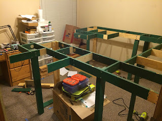
Cuts were made, test fitting the framework:
All three bench work sections assembled and risen:
New Beginnings
After settling in after a much needed move, it's time to get settled on a much needed railroad. I model the Southern Pacific Railroad in July, 1967. My primary focus in on the Oregon Division and it's involvement in the lumber industry. I have toyed around for a long time with ideas on a layout based on the Southern Pacific's Toledo Branch. This line ran from Albany, OR to Toledo, OR after being cut back from Yaquina Bay. Join me and step back in time as a small piece of a vast railroad empire is recreated in 1:160 scale.
Subscribe to:
Comments (Atom)


